UDS (Unified Diagnostic Services) — An Easy Introduction
This document introduces the UDS (Unified Diagnostic Services) protocol and its application in automotive Electronic Control Units (ECUs). The content covers UDS communication methods, client-server architecture, as well as diagnostic and firmware update functions. It provides a detailed explanation of the UDS message structure, including Protocol Control Information (PCI) and Service Identifiers (SID). In addition, it introduces specific applications of UDS such as reading Diagnostic Trouble Codes (DTCs), extracting parameter data, and initiating diagnostic sessions.
1. What is the UDS Protocol?
Unified Diagnostic Services (UDS) is a communication protocol widely used in automotive Electronic Control Units (ECUs). This protocol mainly supports tasks such as diagnostics, firmware updates, and routine testing. UDS (i.e., ISO 14229) is a cross-manufacturer and cross-technology standard that supports multiple communication methods, including CAN, KWP2000, Ethernet, and LIN. Currently, almost all ECUs from Tier-1 suppliers and OEMs use this protocol.
In practical applications, UDS follows a client-server communication model. Here, the diagnostic tool acts as the client, while the vehicle ECU acts as the server. For example, by connecting a CAN interface to the vehicle’s OBD2 connector, UDS requests can be sent to the vehicle. If the ECU supports UDS, it will respond accordingly.
Reading/clearing Diagnostic Trouble Codes (DTCs) to troubleshoot vehicle issues.
Extracting parameter data values such as temperature, State of Charge (SoC), VIN, etc.
Initiating diagnostic sessions, such as testing safety-critical features.
Updating controller software through firmware flashing.
2. UDS Message Structure
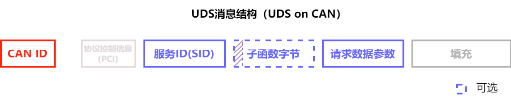
2.1 Protocol Control Information (PCI)
Although the PCI field is not directly related to the specific content of the UDS protocol, it is essential when sending UDS requests over the CAN bus. In simple terms, the PCI field length ranges from 1 to 5 bytes. It contains key parameters that allow long UDS messages to be segmented into multiple shorter CAN frames. This part belongs to the ISO-TP protocol, which defines how such segmentation and transmission are performed.
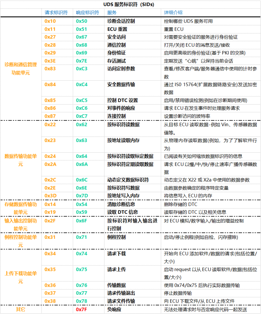
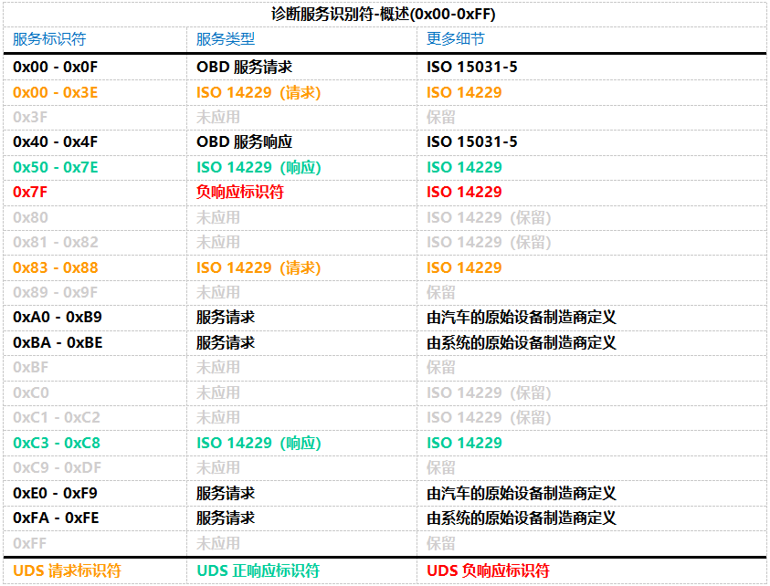
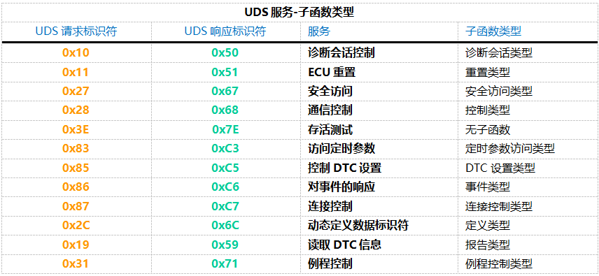
2.2 Service ID (SID)
To use different UDS services, you must use specific UDS Service Identifiers (SIDs).A positive response ID is typically the request identifier plus 0x40.
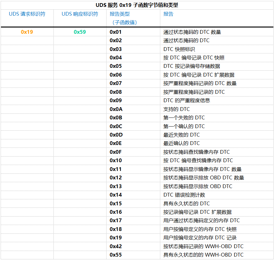
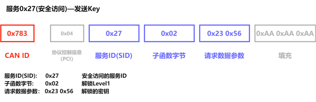
2.3 Sub-function Byte
0x01: Number of DTC by Status Mask
0x02: DTC by Status Mask
0x04: DTC Snapshot Record by DTC Number
0x0A: Supported DTCs
0x55: Permanent WWH-OBD DTCs
2.4 Request Data Parameters

3. UDS Response Structure
3.1 UDS Positive Response
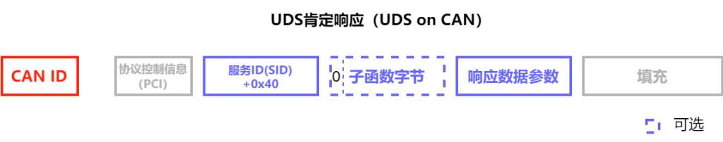
When a vehicle’s Electronic Control Unit (ECU) receives a UDS request and is able to process it normally, it sends back a positive response. The structure of this positive response is very similar to the structure used in the request. For example, if you send a service request 0x22 to obtain specific data, the ECU’s positive response will start with the response service identifier 0x62 (which is the request identifier 0x22 plus 0x40), followed by the 2-byte Data Identifier (DID), and then the actual data for the DID you requested.
The specific structure of the positive response message for each service may vary depending on the type of service. However, in general, the ECU’s reply will confirm whether the request was successful and provide the data you need. This approach ensures clear communication of information and effective resolution of issues.
3.2 UDS Negative Response
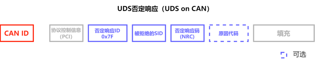
- Byte 1: Protocol Control Information (PCI) — This part is unrelated to the specific operation of UDS, but it is a necessary component of the UDSonCAN response message.
- Byte 2: Negative Response Identifier — This byte is fixed at 0x7F, used to identify that this is a negative response.
- Byte 3: Rejected Service Identifier (SID) — This will display the SID that was used in your original request.
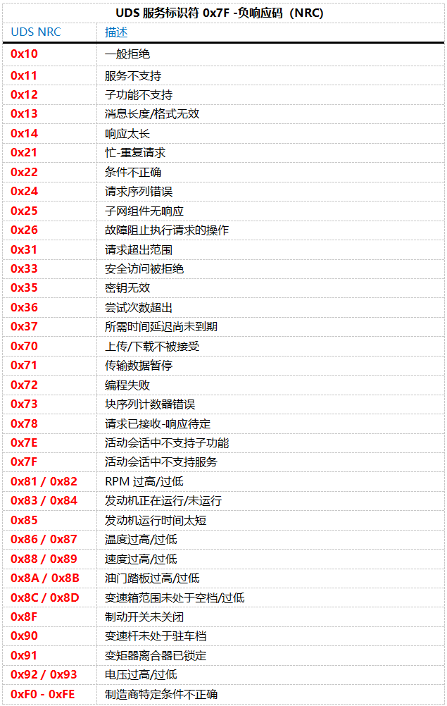
- Byte 4: Negative Response Code (NRC) — This code provides the specific reason why the request failed, such as “Service Not Supported” or “Invalid Format,” etc.
- Byte 5: Reason Code — This appears only when the NRC is 0x22 (Conditions Not Correct), further explaining the detailed reason for the rejection.
Such a response structure allows you to clearly understand the specific reason for the request failure and adjust your diagnostic strategy accordingly. In this way, technicians can more effectively identify problems and take appropriate measures to resolve them.
4. UDS vs. CAN Bus
In the OSI 7-layer model, the CAN bus protocol covers the Physical Layer and Data Link Layer (ISO 11898).In contrast, the UDS protocol covers the Session Layer and Application Layer (ISO 14229).
The relationship can be summarized as: CAN bus is the transportation, while UDS is the language of the diagnostic information.
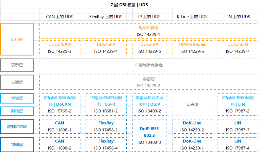
ISO 14229-1 (Application Layer)
The communication process between client and server, including interaction models such as requests and responses.
Various specific UDS service functions.
Encoding for positive and negative responses (Negative Response Codes, NRCs).
Other relevant definitions, such as Diagnostic Trouble Codes (DTCs) and Data Identifiers (DIDs).
ISO 14229-3 (UDS on CAN Application Layer)
The primary goal of ISO 14229-3 is to implement Unified Diagnostic Services (UDS) on the CAN bus, known as UDSonCAN.This standard does not define the specific implementation of any particular vehicle CAN bus architecture; rather, it adds specific requirements and restrictions tailored for UDSonCAN.Specifically, ISO 14229-3 outlines which UDS services have specific requirements when applied to CAN.Among these, affected services include Response On Event, Periodic Identifiers, and data reading operations; these CAN-specific requirements are exhaustively detailed in the standard.
Beyond these, all other UDS services follow the provisions of ISO 14229-1 and ISO 14229-2.Furthermore, ISO 14229-3 describes the mapping relationship between ISO 14229-2 and ISO 15765-2 (ISO-TP), as well as the specific requirements for 11-bit and 29-bit CAN IDs when using UDS and OBD.
ISO 14229-2 (Session Layer)
ISO 15765-2 (Transport + Network Layer for CAN)
For UDS based on CAN, the ISO 15765-2 standard plays a core role, describing the implementation mechanism for diagnostic requests and responses in detail.Specifically, the standard explains how to transmit large data payloads through the combination of multiple CAN frames.This process is a key step in implementing UDSonCAN, ensuring the smooth delivery and processing of complex data.
ISO 11898 (Physical + Data Link Layer for CAN)
5. ISO 15765-3 vs. ISO 14229-3
The definition of UDS on the CAN bus was previously described in ISO 15765-3:2004.However, in 2012, this content was moved to ISO 14229-3, which now specifically covers Unified Diagnostic Services on CAN (UDSonCAN).
6. Is UDS Data Public?
While the UDS protocol framework is a standard, the interpretation of the data itself is often a secret held by the manufacturer.
For example, reading a specific temperature value may require knowing a custom DID that is only documented in internal manufacturer files.Standardized access is mostly restricted to emissions-related data (OBDonUDS).
7. Why is UDS Becoming More Important?
UDS is gradually replacing traditional OBD2 standards through frameworks like WWH-OBD and OBDonUDS.
This is particularly crucial for Electric Vehicles (EVs), as standard OBD2 cannot read EV-specific information like Battery State of Charge (SoC) or State of Health (SoH).
8. Software Customization Development (Dots)
Customizing UDS PC software allows for the creation of tools that perfectly fit specific diagnostic, flashing, and monitoring needs.
Our professional development services cover requirements analysis, system design, coding, and testing to automate vehicle testing workflows.
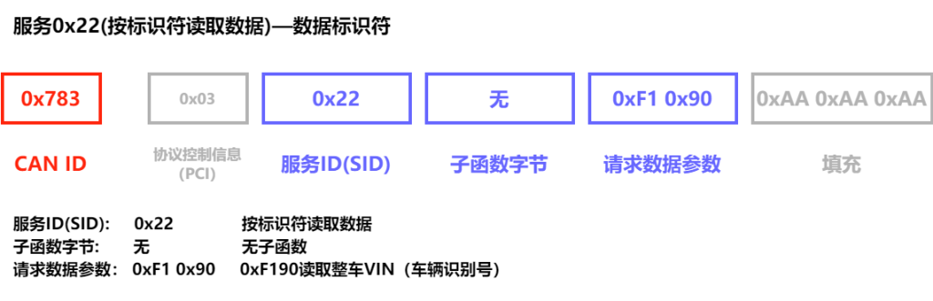
Example 1: Decoding DID Data (VIN Number)
Send Request: 03 22 F1 90 AA AA AA AA (Using SID 0x22 and DID 0xF190)
Receive Response: 62 F1 90 [Data…] (Response 0x62 contains the VIN in ASCII format)
Example 2: Reading DTCs (Clutch Position Sensor Short to Ground)
Request: 03 19 02 08 AA AA AA AA (Mask 0x08 for historical faults)
Response: 07 59 02 08 08 05 11 2F (Where 08 05 11 is the DTC code and 2F is the status)
Example 3: Firmware Flashing (Flash Programming)
Unified Diagnostic Services (UDS) is an incredibly practical tool for vehicle communication, extending beyond diagnostics and security testing. It can also be used to update the firmware of a vehicle’s Electronic Control Units (ECUs). While the UDS flashing process may vary slightly across different manufacturers and controllers—requiring adjustments based on specific OEM requirements—the basic workflow generally follows these steps:
Start Diagnostic Session: First, we initiate an extended session using the Diagnostic Session Control service (SID=0x10). This session type grants the necessary permissions for write operations and other high-privilege tasks.
Security Access: The Security Access service (SID=0x27) ensures that only authorized tools can perform write operations or other sensitive tasks. This typically involves a request-and-response seed/key exchange to prevent unauthorized access.
Request Download or Upload: Next, we prepare for the data transfer using the Request Download (SID=0x34) or Request Upload (SID=0x35) services. This step involves specifying parameters such as the data size and the target memory address.
Transfer Data: The Transfer Data service (SID=0x36) is used for the actual delivery of data. In the case of a firmware update, the diagnostic tool sends the firmware data in several sequential packets to the ECU.
Exit Transfer: The Request Transfer Exit service (SID=0x37) marks the completion of the data transfer. At this point, the ECU begins processing the received data, such as writing the new firmware into flash memory.
ECU Reset: Once the update is complete, the ECU Reset service (SID=0x11) is typically used to reboot the ECU, ensuring that the new firmware is correctly loaded and executed.
This constitutes the fundamental workflow of UDS flashing. Although specific steps—such as service details or the exact sequence—may vary between manufacturers or controllers based on hardware and software requirements, the core objective remains the same: ensuring that firmware is updated safely and effectively. This process allows vehicle systems to remain up-to-date and operate smoothly.
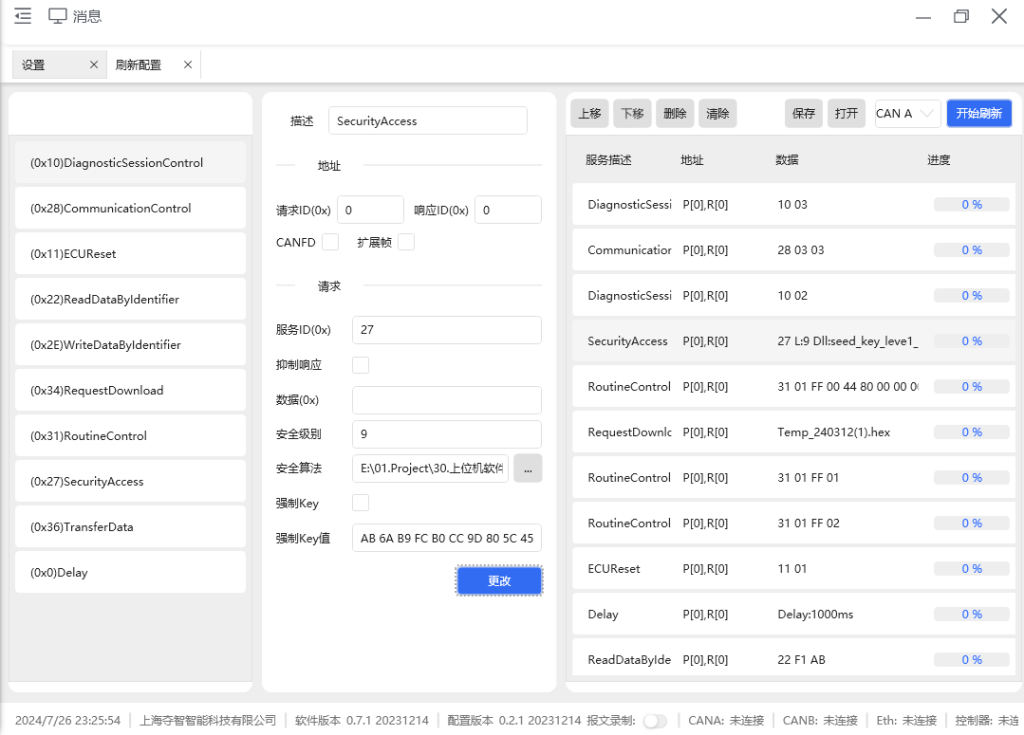
In our Dots customized development services, we offer highly flexible solutions designed to precisely meet the specific requirements of various manufacturers. Whether executing standard flashing sequences or complex customized operations, customers can configure their own flashing workflows according to their needs, enabling rapid response to the demands of different projects.
Furthermore, we utilize broadcast flashing technology, which allows for the simultaneous batch flashing of multiple controllers on the factory production line. By transmitting firmware update packages to multiple controllers at once through broadcasting, this technology significantly saves time.