10Base-T1S: A Quick Start Guide
1. Introduction: Why Does the Automotive World Need a "Different" Type of Ethernet?
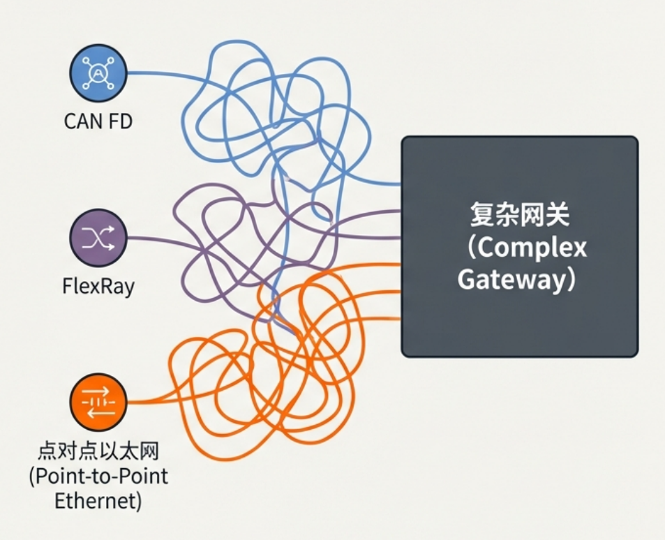
1.1 Current Challenges in Automotive Networking
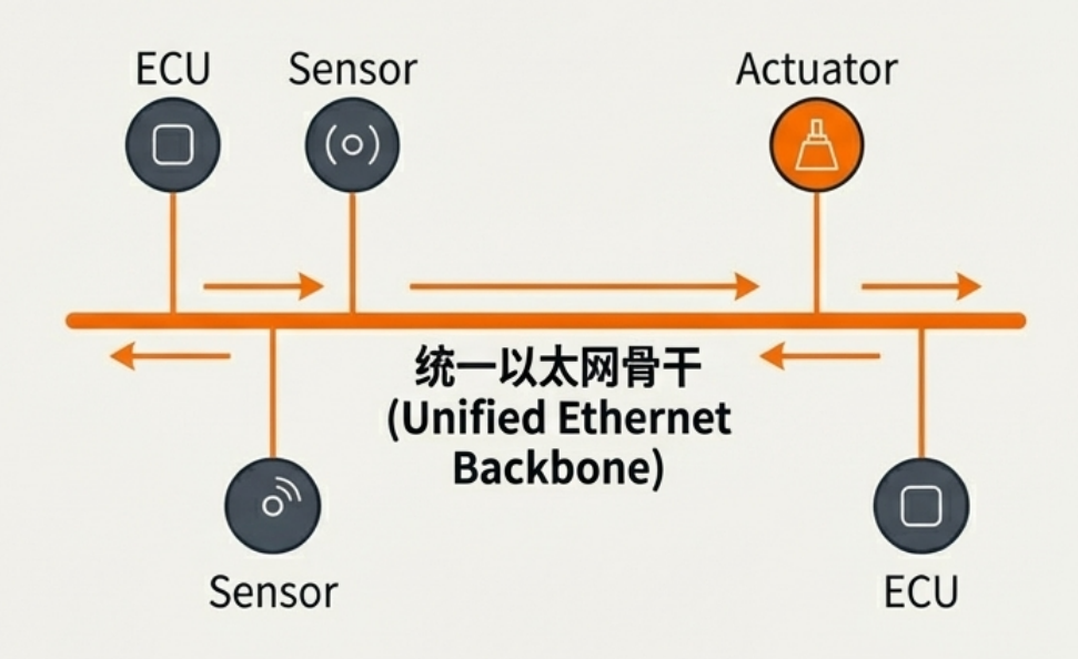
1.2 The Vision of the "All-Ethernet" Car
1.3 Limitations of Traditional Ethernet and the Birth of 10Base-T1S
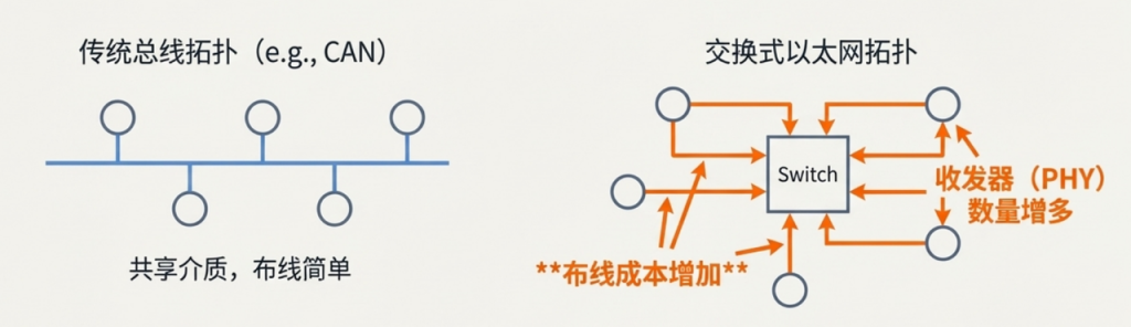
- Wiring and Cost: Traditional Ethernet typically uses a four-wire or eight-wire system, whereas automotive buses (like CAN) generally use a single twisted pair. Fewer cables mean lower costs and lighter weight. Additionally, point-to-point or switched Ethernet topologies require more transceivers (PHYs), further increasing hardware costs.
- Electromagnetic Compatibility (EMC): The electromagnetic environment in a vehicle is extremely harsh, and its EMC requirements are far higher than those for consumer electronics. Standard Ethernet cannot meet these demands.
- Power Modes: Vehicles have extreme power consumption requirements when the engine is off to prevent battery drain. Standard Ethernet lacks such ultra-low-power sleep modes.
- Wake-up Time: Automotive ECUs must be able to fully wake up from sleep and be operational within 100 milliseconds—a target unreachable for standard Ethernet.
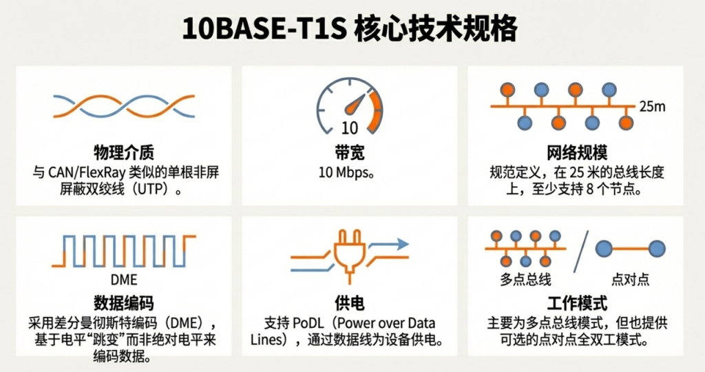
2.What is 10Base-T1S? 什么是 10Base-T1S?
Core Features at a Glance The following table summarizes the key technical parameters of 10Base-T1S:
| Feature | Description |
| Technology Name | 10BASE-T1S |
| Data Rate | 10 Mb/s |
| Network Topology | Multi-drop or Bus |
| Physical Medium | Single Twisted Pair (UTP), similar to cables used by CAN FD or FlexRay. |
| Nodes & Length | Supports at least 8 nodes; maximum bus length of 25 meters. |
| Data Encoding | DME (Differential Manchester Encoding): Encodes data based on signal “transitions” rather than absolute voltage levels. (This method provides an inherent clock signal for reliable data recovery at the receiver). |
3. Core Mechanism: How PLCA Works
3.1 The Fundamental Problem of Bus Networks
CAN: Non-destructive arbitration (nodes with lower IDs/higher priority win bus access).
FlexRay: Time Division (each node has a fixed time slot to transmit, preventing collisions at the source).
3.2 The PLCA Mechanism
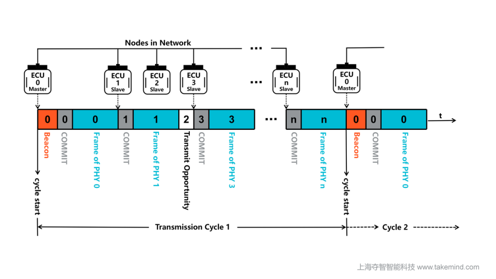
Node ID: Each node in the network is assigned a unique ID from 0 to N, which determines its transmission order in the communication cycle.
Master Node: Usually the node with ID 0. It acts as the network coordinator and is responsible for periodically sending a “Beacon” to start a new communication cycle.
Beacon: A special signal sent by the Master Node that marks the start of a new transmission cycle and synchronizes the timing of all nodes on the network.
Commit Symbol: If a node has data to send during its transmission opportunity, it first sends a “Commit Symbol”. This symbol is crucial—it’s like “raising a hand to speak” in a meeting, clearly indicating that it will occupy the bus. This behavior distinguishes it from nodes that simply let their opportunity expire silently. After sending the Commit Symbol, the node immediately begins sending standard Ethernet data frames.
- Transmit Opportunity (TO): After the Master Node sends the Beacon, all nodes receive a dedicated time window to send data, strictly in ascending order of their ID numbers.
4. PLCA in Action: Analysis of Common Scenarios
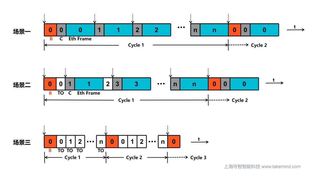
4.1 Scenario 1: All Nodes Have Data to Send
- Node 0 sends the Beacon to start the cycle.
- Node 0’s transmission opportunity arrives. Since it has data, it immediately sends a “Commit Symbol” followed by a full Ethernet data frame.
- Next is Node 1’s opportunity; it also sends its “Commit Symbol” and data frame.
- This process continues until all nodes have been polled.
4.2 Scenario 2: Partial Nodes Have Data to Send (e.g., Nodes 1 and 3)
- Node 0 sends the Beacon to start the cycle.
- Node 0’s opportunity arrives and expires because it has no data.
- Next is Node 1’s opportunity. Since it has data, it sends a “Commit Symbol” and its data frame.
- After Node 1 finishes, it’s Node 2’s turn, but it has no data, so the opportunity expires.
- Then Node 3 takes its turn, sending a “Commit Symbol” and its data frame.
- The process continues until all nodes are polled.
4.3 Scenario 3: Idle Network (No Nodes Have Data)
- Node 0 (Master) sends the Beacon to start a new cycle.
- It is Node 0’s transmission opportunity, but since it has no data to send, the opportunity automatically expires after a brief window.
- It is then Node 1’s transmission opportunity; it also has no data to send, so the opportunity expires as well.
- This process continues sequentially until the transmission opportunities for all nodes have been polled and expired. Then, the Master Node will send the Beacon again to start the next cycle.
5. PLCA in Action: Analysis of Optimized Scenarios
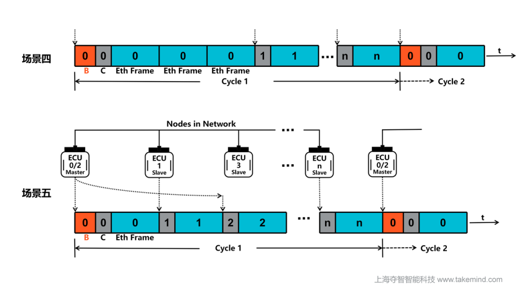
5.1 Scenario 4: Burst Mode
5.2 Scenario 5: Multiple IDs for a Single Node
6. PLCA in Action: Analysis of Special Scenarios
6.1 Scenario 6: A Slave Node (Non-ID 0) Unexpectedly Goes Offline
- Network Stability: The communication cycle and other nodes are unaffected.
- Diagnostics: While the physical layer remains normal, upper-layer protocols will detect the lost heartbeat or data to determine the node is offline.
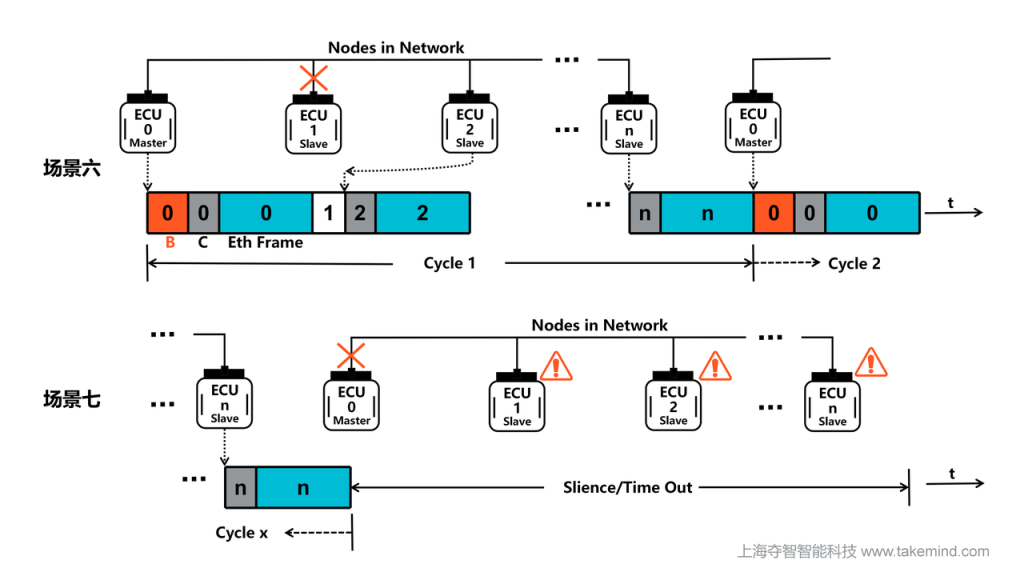
6.2 Scenario 7: The Master Node (ID 0) Unexpectedly Goes Offline
Network Stability: Since only the Master sends the “Beacon,” its loss means no new cycles can start once the current one ends.
Diagnostics: Some PHY chips have a beacon-loss timer; if no beacon is received for a long time, the PHY may fallback to the CSMA/CD model. This keeps communication alive but loses the collision-free and deterministic advantages of PLCA. Alternatively, the application layer can trigger a backup Master
6.3 Scenario 8: Two Slave Nodes Wrongly Configured with the Same ID
When the TO for the duplicate ID arrives, both nodes will attempt to claim the bus simultaneously.
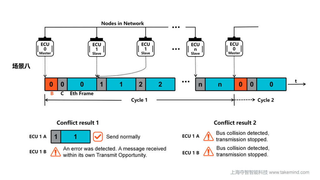
Network Stability: A Collision occurs at the physical layer. Waveform distortion prevents the receiver from parsing valid data (CRC failure). While scheduling doesn’t stop, efficiency for that ID and subsequent nodes drops significantly.
Diagnostics: PHY chips trigger status registers: RXINTO (Receive in TO) or TXCOL (Transmit Collision). These are key tools for debugging ECU flashing or configuration errors.
6.4 Scenario 9: Two Nodes Wrongly Configured as ID 0 (Master)
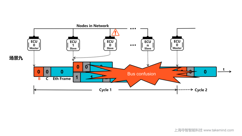
Network Stability: Synchronization collapse. Overlapping or out-of-order beacons prevent slaves from locking onto a sync frequency, paralyzing the PLCA cycle.
Diagnostics: PHYs feature “Multi-Master Detection”. A node configured as ID 0 that receives another beacon will set the UNEXPB (Unexpected BEACON Received) flag in the STS1 register.
6.5 Scenario 10: Master's MAX_ID Configuration is Lower than the Highest Node ID
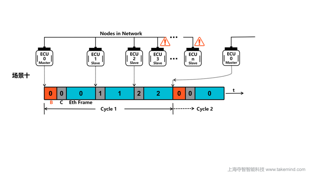
Network Stability: High-ID nodes are “silenced”. The Master sends a new beacon immediately after ID 2’s turn, so IDs 3-6 never get their opportunity.
Diagnostics: Affected slaves will trigger the BCNBFTO (BEACON Received Before Transmit Opportunity) flag in the STS1 register, proving the Node Count mismatch.
7. Advantages: Why Choose 10Base-T1S?
7.1 Core Advantages
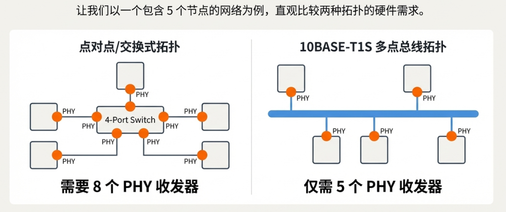
- Reduced Hardware Cost and Wiring Weight: Connecting 5 ECUs via 10BASE-T1S requires only 5 transceivers (PHYs). A switched point-to-point solution would require 10 PHYs (5 in the ECUs and 5 on the switch). Fewer PHYs and simpler wiring lead to lower costs and lighter vehicles.
- Enabling All-Ethernet Architecture: 10BASE-T1S fills a critical gap, allowing a unified technology (Ethernet) to cover everything from high-bandwidth systems to low-cost sensors/actuators. This greatly simplifies the overall vehicle network architecture.

7.2 Engineering Practice: Beyond Standard Limits
Node Capacitance: Every component (PHY, connector, ESD protection) adds capacitance. The standard assumes 25pF per node; keeping this at 20pF or lower is essential for increasing node counts.
Node Spacing: Physical distance affects signal integrity. Ford’s research provides specific spacing recommendations:
8 Nodes: Min. 0.5m spacing.
8-10 Nodes: Min. 0.75m spacing.
10-15 Nodes: Min. 1.0m spacing.
15-20 Nodes: Min. 1.5m spacing.
This insight transforms theoretical standards into actionable engineering guidelines: by optimizing topology design and component selection, it is entirely possible to achieve a stable network with more than 8 nodes. Of course, the final design must undergo rigorous signal integrity testing to ensure all parameters comply with specifications.