Automotive ECU Breakout Box
1. What Is an Automotive Breakout Box?
An automotive Breakout Box (BOB) is an interface device designed to expose otherwise inaccessible electrical connections between an Electronic Control Unit (ECU), vehicle wiring harness, and external testing equipment.Common names include:Breakout Box (BOB)、ECU Breakout Box、ECU Adapter Box、Automotive Adapter Box、OBD Breakout Box、Fault Simulation Box.Simply put, a breakout box is not an ECU itself. It serves as an accessible interface layer within the controller testing system.
Instead of repeatedly probing ECU connectors, stripping wires, or making temporary wiring modifications, engineers can access individual electrical signals through dedicated panel interfaces.These signals may include:
Power supply and ground
CAN / CAN FD / LIN communication
Automotive Ethernet
Analog and digital signals
Sensor inputs
Actuator outputs
PWM and frequency signals
Depending on its configuration, a breakout box can support signal measurement, connection switching, circuit interruption, short-circuit simulation, load insertion, and external test system integration.

Common Breakout Box Configurations:
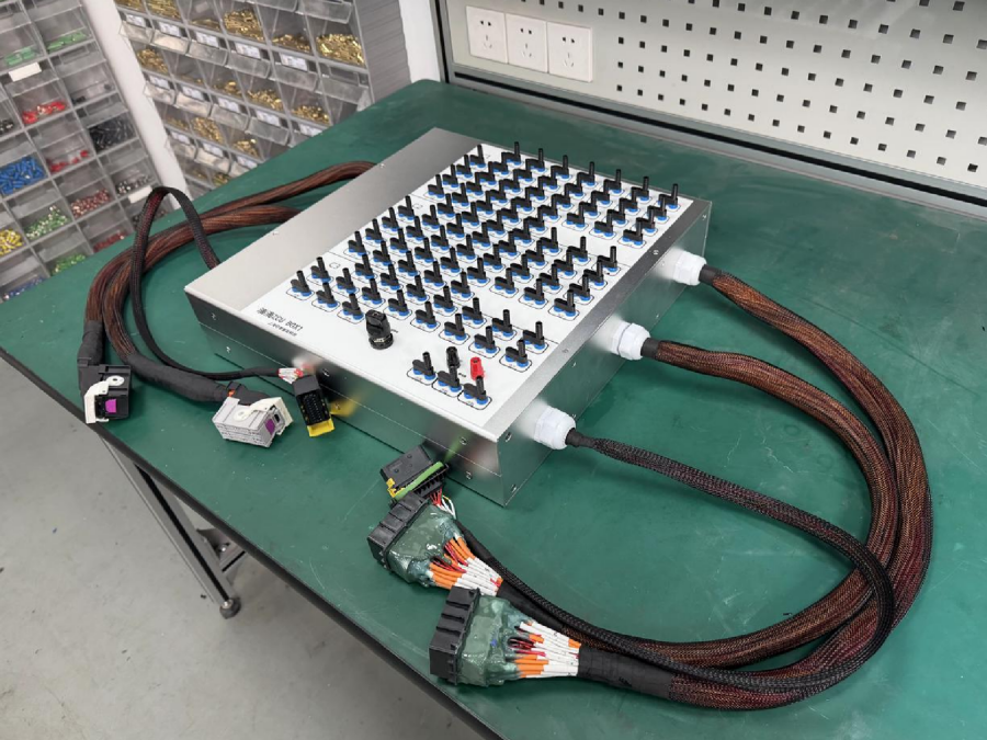
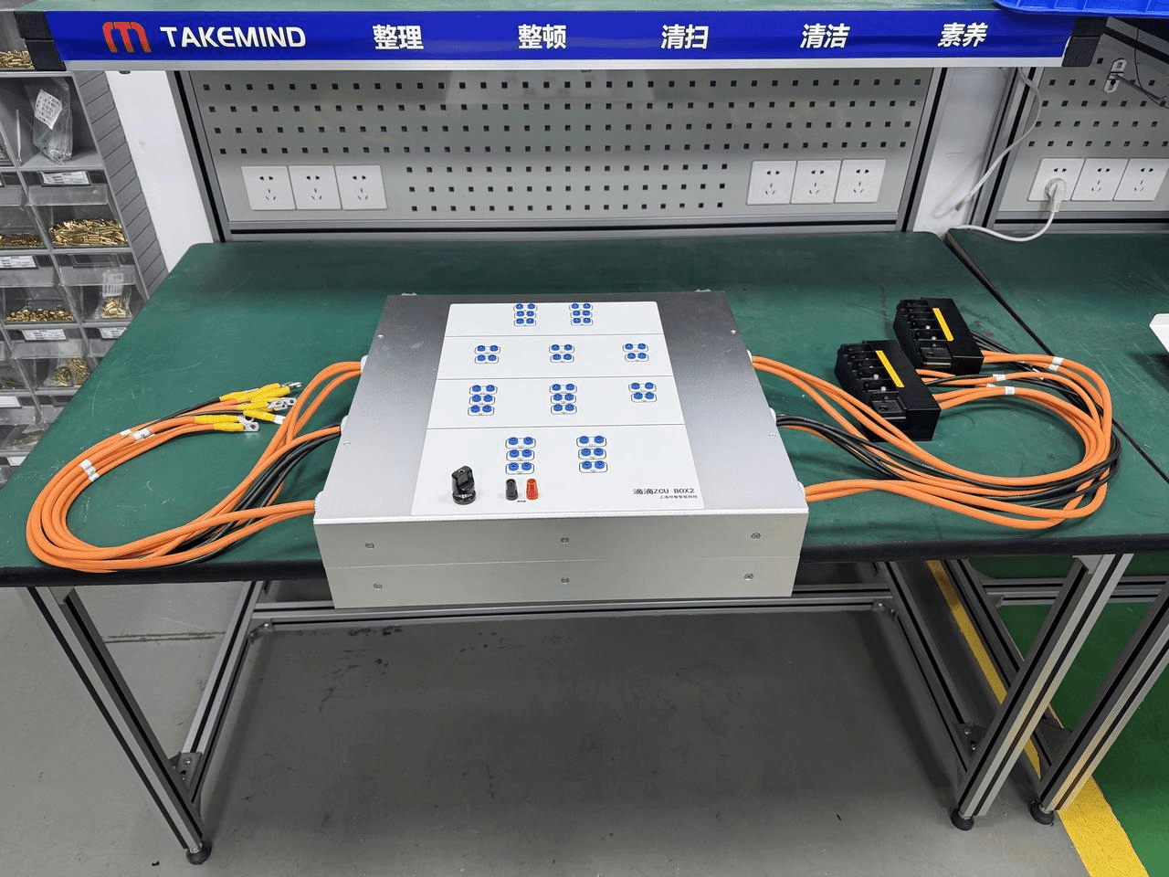
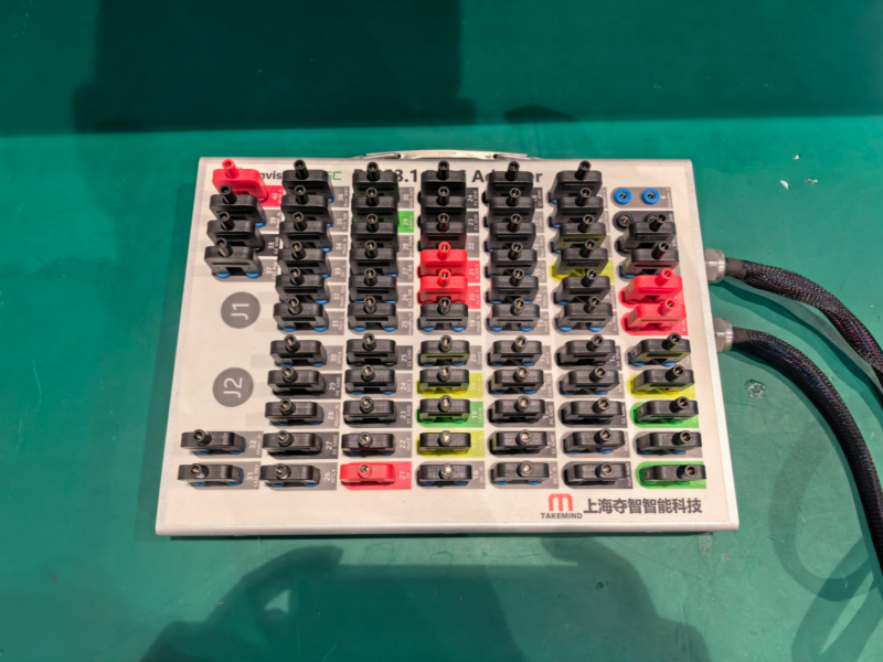
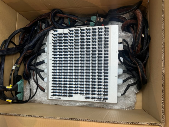
Dedicated ECU Breakout Box:One side uses an OEM-compatible female connector to connect to the ECU, while the other side connects to the vehicle or HIL wiring harness through a matching connector.Individual ECU pins are routed to accessible interfaces such as 4 mm banana sockets, D-sub connectors, terminal blocks, relay channels, or jumper positions.
Universal Breakout Box:A universal breakout box connects standard interfaces, such as banana sockets and D-sub connectors, to standardized industrial circular connectors.Customized adapter harnesses connect the standardized interface to different ECU connectors, allowing the same basic test platform to support multiple controller types.
2. Typical Applications of Automotive Breakout Boxes
| Application | Main Users | Typical Purpose | Equipment Configuration |
|---|---|---|---|
| ECU Development and Debugging | ECU / VCU / BMS / Domain Controller Engineers | Access controller pins and verify signal inputs, outputs, and communication | ECU + BOB + Oscilloscope / Multimeter / CAN Tools |
| HIL / SIL Testing | Test Engineers | Connect ECUs to real-time simulators for automated testing and fault injection | ECU + BOB + HIL Rack + Load Box |
| Production / EOL Testing | Manufacturing Test Engineers | Enable quick connections and inspection of power, communication, and critical I/O | DUT + Test Harness + BOB / Adapter |
| After-sales Diagnostics and Repair | Service Technicians | Measure diagnostic and sensor circuits without modifying original wiring | Vehicle + OBD BOB + Diagnostic Tool / Multimeter |
| ECU Bench Programming | Calibration / Repair / Programming Engineers | Supply power to ECUs and establish diagnostic communication outside the vehicle | ECU + Bench Adapter + Programmer |
| Wiring Harness Troubleshooting | Wiring Harness / Electrical Engineers | Identify short circuits, open circuits, pin misalignment, and poor connections | Harness + BOB + Pinout Diagram + Measuring Instruments |
3. Core Function 1: Pin Signal Access and Measurement
3.1 Function Overview
Pin signal access is the most fundamental and frequently used function of a breakout box.ECU connectors typically contain densely arranged pins. Direct probing can easily cause probe deformation, accidental short circuits, or terminal damage.A BOB routes individual ECU pins to clearly identified panel interfaces, allowing engineers to connect multimeters, oscilloscopes, logic analyzers, CAN/LIN analyzers, and data acquisition devices.
Common interface types include:
4 mm Banana Sockets: Suitable for multimeters, power supplies, load boxes, and oscilloscope probes.
D-sub / IDC / Terminal Blocks: Suitable for multi-channel data acquisition and HIL integration.
LED Indicators: Used in some OBD and low-voltage signal breakout boxes to indicate power, ground, and communication activity.
3.2 Practical Example
Consider testing whether an ECU ignition input, KL15, is functioning correctly.The engineer connects the ECU to the BOB and connects the vehicle or test bench wiring harness to the opposite side.The corresponding KL15 pin is then accessed through the breakout box panel.
After switching on the ignition, a multimeter can be used to measure whether the voltage between KL15 and ground is approximately 12 V. An oscilloscope can simultaneously monitor the voltage during power-up to identify voltage drops, transient spikes, or intermittent contact.Without a BOB, engineers may need to probe the rear of the ECU connector or modify the wiring harness.
With a BOB, measurements can be performed directly through accessible panel interfaces, reducing testing time and the risk of connector or wiring damage.
3.3 Key Benefits
Reduce the time required to locate electrical faults.
Protect original ECU terminals and vehicle wiring harnesses.
Enable multiple engineers to reproduce the same tests using consistent pin references.
Provide convenient access to high-density and mixed-signal connectors.
4. Core Function 2: Interface Adaptation Between Controllers and Test Systems
4.1 Function Overview
Different ECUs use different connectors, pin assignments, and wiring harness configurations.Meanwhile, HIL systems, data acquisition devices, load boxes, and fault injection equipment often rely on standardized interfaces.An Adapter Box bridges this gap by converting controller-specific connectors into standardized test system interfaces.
Typical configurations include:
ECU connectors to HIL rack D-sub or matrix interfaces.
ECU connectors to banana jack panels.
Vehicle wiring harness interfaces to laboratory test terminals.
OBD diagnostic connectors to individually accessible power, ground, CAN-H, CAN-L, and K-Line connections.
4.2 Practical Example
A motor controller project requires integration with a HIL system.The controller uses a 121-pin connector, while the HIL rack uses standard multi-channel D-sub interfaces.A customized Adapter Box can be developed with clearly labeled ECU pin numbers and signal names on the front panel, while the rear interfaces connect directly to the HIL system.
When switching to another controller, engineers only need to replace the corresponding Adapter Box or adapter harness instead of rebuilding the internal wiring of the entire HIL rack.
4.3 Key Benefits
Reduce coupling between the test system and specific ECU models.
Simplify project changes by replacing only the adapter box or wiring harness.
Standardize connections between supplier ECUs, customer wiring harnesses, and in-house testing equipment.
Convert complex wiring configurations into reusable test fixtures and reduce manual wiring errors.
5. Core Function 3: Fault Injection and Failure Simulation
5.1 Function Overview

Fault injection is an important function in automotive controller validation.It verifies whether an ECU can correctly detect electrical faults, activate protection mechanisms, and enter appropriate degraded operating modes under abnormal conditions.
A breakout box can be integrated with dedicated fault simulation circuits or relay matrices to simulate various electrical failures.
<Typical Fault Injection Types>
Open Circuit: Disconnect a sensor, actuator, or communication line to verify whether the ECU detects the corresponding Diagnostic Trouble Code (DTC).
Short to Ground: Connect a signal line to GND to simulate damaged wiring contacting the vehicle chassis.
Short to Power: Connect a signal line to VBAT or 5 V to simulate incorrect electrical connections.
Signal-to-Signal Short Circuit: Connect two signal lines together, such as simulating CAN-H/CAN-L faults or sensor signal interference.
Contact Resistance Simulation: Insert a resistor into a circuit to simulate oxidized terminals or poor electrical contact.
Abnormal Load Simulation: Switch between open-circuit loads, overload conditions, low-resistance loads, or simulated actuator loads.
5.2 Practical Example
Consider testing the temperature sensor diagnostics of a Battery Management System (BMS).Under normal conditions, an NTC temperature sensor signal is connected to the BMS through the breakout box.
The test engineer can perform the following steps:
Disconnect the NTC signal through the BOB panel and check whether the BMS reports an open-circuit fault within the specified time.
Short the signal to ground and verify whether the BMS detects a short-to-ground fault.
Insert a fixed resistor to simulate an extreme temperature condition.
Verify whether the thermal management strategy activates power limitation or protection measures as expected.
5.3 Key Benefits
Support ISO 26262-related validation, diagnostic coverage, and fault response testing.
Reproduce electrical faults repeatedly on a test bench without performing potentially dangerous operations on a real vehicle.
Enable automated fault injection through relay matrices or HIL control.
Help engineers distinguish software diagnostic logic issues from wiring harness or hardware connection problems.
6. Core Function 4: Communication Network Testing

6.1 Function Overview
Modern automotive controllers use multiple communication technologies, including CAN, CAN FD, LIN, FlexRay, Automotive Ethernet, and K-Line.A breakout box provides safe access to communication wiring, making it easier to connect bus analyzers, diagnostic tools, termination resistors, gateway simulators, and packet capture equipment.
Typical testing activities include:
Measuring CAN-H and CAN-L static voltages and differential waveforms.
Checking whether CAN bus termination resistance is approximately 60 Ω.
Connecting tools such as CANoe, CANalyzer, PCAN, and Kvaser for message monitoring.
Verifying LIN master/slave node wake-up, scheduling tables, and signal levels.
Checking OBD diagnostic pins, including CAN on pins 6 and 14, K-Line on pin 7, power on pin 16, and ground on pins 4 and 5.
Adapting automotive Ethernet interfaces to standard test interfaces for link verification and packet capture.
6.2 Practical Example
A vehicle ECU cannot be accessed through a diagnostic tool.The engineer connects an OBD Breakout Box to the vehicle’s OBD port and then connects the diagnostic tool to the breakout box.
The following checks can be performed:
Verify that pin 16 provides approximately 12 V.
Check that pins 4 and 5 have reliable ground connections.
Measure CAN voltage levels and termination resistance on pins 6 and 14.
If CAN-L is found to be pulled low, disconnect related controllers or use additional wiring breakout points to isolate the faulty network segment.
6.3 Key Benefits
Quickly distinguish communication problems caused by power supply, grounding, physical-layer faults, or software protocols.
Connect multiple diagnostic and analysis tools without modifying the original diagnostic interface.
Support simultaneous ECU flashing, diagnostics, and message monitoring.
Improve troubleshooting efficiency in vehicle network diagnostics and EOL communication testing.
7. Core Function 5: Power Supply, Grounding, and Current Measurement
7.1 Function Overview
ECU power supply and grounding quality directly affect startup, programming, communication, and functional stability.A breakout box can expose critical power and ground signals, including:VBAT、IGN、KL15、KL30、KL31、5 V sensor power supply、Internal reference ground.
These signals can then be accessed for voltage, current, voltage drop, and transient waveform measurements.
Common functions include:
Connecting an ammeter or current clamp in series with the power supply line.
Measuring ECU inrush current during power-up.
Checking ground voltage drops and potential differences between ground points.
Providing a stable power supply for bench-tested ECUs.
Monitoring power supply stability during diagnostic programming.
Integrating fuses or protection circuits to reduce the risk of damage caused by incorrect connections.
7.2 Practical Example
An ECU programming process occasionally fails.Using a breakout box, the engineer connects an oscilloscope and current probe to the power supply lines.During the Flash memory erase stage, the current increases while voltage drops across the wiring harness cause the ECU supply voltage to fall below its required threshold.After upgrading the power cable specifications or increasing the test bench power supply capacity, the programming failures are eliminated.
7.3 Key Benefits
Quickly identify power-up failures, abnormal sleep current, and programming interruptions.
Verify power management strategies and wake-up/sleep current consumption.
Integrate test power supplies, fuse protection, and ECU connections into a fixed test fixture.
8. Core Function 6: Sensor, Actuator, and Load Integration
8.1 Function Overview
A breakout box is not limited to signal measurement. It can also connect sensor simulators, actuator loads, actual loads, and electronic load boxes to an ECU.In HIL applications, the real vehicle environment is replaced by a real-time simulator.In repair and ECU bench applications, external sensors or actuators may need to be simulated to satisfy the ECU’s startup or communication requirements.
Typical devices and signals include:
NTC/PTC temperature sensor simulation resistors.
Analog voltage signals for accelerator pedals, pressure sensors, and other sensors.
Digital switching inputs, PWM inputs, and frequency inputs.
Relay, lamp, solenoid valve, and motor actuator loads.
Resistive loads, electronic loads, and fault simulation loads.
HIL analog outputs, digital I/O, and load simulation modules.
8.2 Practical Example
Consider testing injector diagnostics on an engine control unit.Connecting actual injector loads for extended testing may be inconvenient.The test engineer uses a breakout box to connect the ECU injector driver outputs to an electronic load.The load simulates the normal electrical characteristics of an injector. The engineer can then switch between normal, open-circuit, and low-resistance conditions to verify whether the ECU correctly identifies driver circuit faults.
8.3 Key Benefits
Enable ECU operation without requiring a complete vehicle.
Support automated testing across different sensor operating ranges.
Protect real actuators from repeated fault injection and potential damage.
Allow flexible switching between actual and simulated loads.
9. Core Function 7: ECU Bench Programming, Flashing, and Standalone Debugging
9.1 Function Overview
An ECU Bench Adapter allows an ECU to operate independently of the vehicle by providing the necessary power, ground, ignition, and communication connections.These adapters are particularly useful in after-sales service, calibration, repair, and ECU development.
Typical applications include:
ECU programming and calibration outside the vehicle.
Reading ECU information, DTCs, and software versions.
Simulating ignition and wake-up signals.
ECU recovery, backup, and bench communication with programming tools.
Developing diagnostic communication without connecting the ECU to a complete vehicle.
9.2 Practical Example
A TCU has been removed from a vehicle and needs a software update.The engineer uses a Bench Adapter to connect the original TCU connector and route the 12 V power supply, ground, ignition, and CAN signals to a programming tool.
After verifying power stability, the programming software establishes a diagnostic session with the TCU through CAN and completes the flashing process.The breakout box can also provide simultaneous access to CAN waveforms and supply voltage, helping reduce the risk of programming interruptions.
9.3 Key Benefits
Perform bench testing without occupying a complete vehicle.
Reproduce controller communication issues more efficiently during development and maintenance.
Support standalone testing of ECU, TCU, VCU, BMS, and other electronic control modules.
10. Core Function 8: Wiring Harness Manufacturing, Verification, and Troubleshooting
10.1 Function Overview
A breakout box can also serve as a wiring harness verification tool, particularly for projects involving high-pin-count connectors, complex signals, and easily confused wire labels.By mapping individual connector pins to clearly identified panel positions, engineers can systematically inspect terminal crimping, pin assignment, continuity, insulation, shielding, and labeling.
Common inspection items include:
Whether pin-to-pin continuity is correct.
Whether there are misaligned pins, missing terminals, reversed connections, or unlocked terminals.
Whether cable shielding is grounded according to specifications.
Whether power and signal wires have unintended short circuits.
Whether wire labels match the wiring diagrams.
Whether intermittent contact problems occur after cable bending or vibration.
10.2 Practical Example
After connecting an HIL wiring harness, a PWM output behaves abnormally.The engineer identifies the ECU-side pin and HIL-side channel through the breakout box panel.Using a multimeter’s continuity function, the engineer discovers that two adjacent pins were incorrectly swapped during harness assembly.After correcting the terminal positions, the PWM signal returns to normal.
10.3 Key Benefits
Quickly isolate wiring harness problems from ECU or HIL software issues.
Incorporate harness verification into factory inspection and project delivery procedures.
Improve quality control for customized adapter cables, Y-cables, and breakout boxes.
11. Key Requirements When Designing a Customized Breakout Box
To ensure an efficient design, accurate quotation, and reliable manufacturing process, the following technical requirements should be defined before developing a customized breakout box.
| Item | Information to Be Defined |
|---|---|
| Application | ECU / VCU / BMS / TCU / Domain Controller / OBD / Wiring Harness / Sensors / Actuators |
| Connector Specifications | Manufacturer, part number, pin count, male/female type, keying, and mechanical protection |
| Pin Assignment | Pin number, signal name, electrical type, voltage/current rating, and shielding requirements |
| Operating Mode | Direct pass-through, Y-split connection, HIL adaptation, bench power supply, and fault injection |
| Panel Interfaces | Banana sockets, terminal blocks, D-sub, DUT interfaces, fuses, switches, and LEDs |
| Fault Simulation | Open circuit, short to ground, short to power, signal-to-signal short circuit, series resistance, and load switching |
| Safety Protection | Fuses, current limiting, reverse-polarity protection, high-voltage isolation, emergency stop, and grounding strategy |
| Labeling Standards | Panel markings, wire numbers, heat-shrink labels, colors, QR codes, and version numbers |
| Documentation | Schematics, wiring tables, BOM, test reports, operating instructions, and revision records |
Clearly defining these requirements helps ensure that the final breakout box matches the electrical, mechanical, and functional requirements of the target test application.