
Automotive Ethernet Design: Auto-Negotiation
With the rapid development of intelligent connected vehicles, the requirements for bandwidth, latency, and reliability in vehicle networks have grown exponentially. As the core of the next-generation automotive backbone network, the way underlying connections are established in Automotive Ethernet is crucial. Today, we will explore the “prelude” to establishing a physical layer (PHY) connection—Auto-Negotiation (AN). In this article, we will start from the lowest-level encoding rules, dissect the DME page step-by-step, investigate the Master/Slave arbitration logic, and reveal the “black technology” used to prevent deadlocks.
1. The Language of Communication: DME Encoding Rules
Before two devices start “negotiating terms,” they must speak the same language. The Automotive Ethernet auto-negotiation phase utilizes DME (Differential Manchester Encoding).
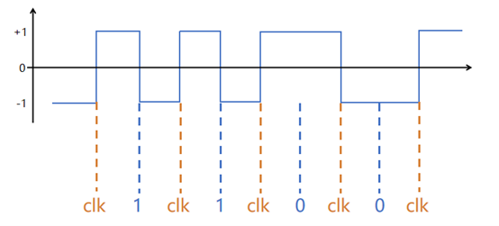
The DME encoding rule is ingenious, as it integrates the clock signal with the data signal:
- Clock Bit (clk): Located at odd-numbered positions, the electrical level always transitions, ensuring the receiver can continuously extract the synchronous clock.
- Data Bit (data): Located at even-numbered positions. If the data is “1”, the level transitions; if the data is “0”, the level remains unchanged. This “self-clocking” encoding method ensures that both parties can accurately identify 0s and 1s, even during the highly unstable initial stages of the link.
This “self-clocking” encoding method ensures that both parties can accurately identify 0s and 1s, even during the highly unstable initial stages of the link.
2. Signaling Frame Structure: The 92-bit DME Page
When a PHY chip begins transmitting auto-negotiation information, the “letters” they send are called DME Pages. A complete DME page consists of 92 bits.
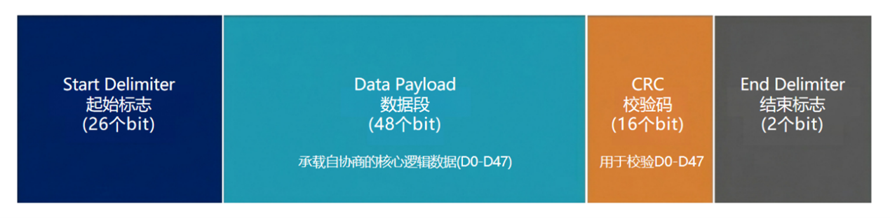
Dissecting this 92-bit frame structure, we can see it is divided into four parts:
- Start Delimiter: Occupies 26 bits, used to wake up the remote end and identify the start of the page.
- Data Payload: Occupies 48 bits (D0-D47). This is the effective data area carrying the core logic of auto-negotiation.
- CRC (Cyclic Redundancy Check): 16 bits, used to verify the integrity of the D0-D47 data and prevent corruption during transmission.
- End Delimiter: 2 bits, indicating the end of the current page transmission.
3. Data Segment Structure: 48-bit Payload Analysis
What exactly is contained within these 48 effective data bits (D0-D47)? Let’s break them down further.
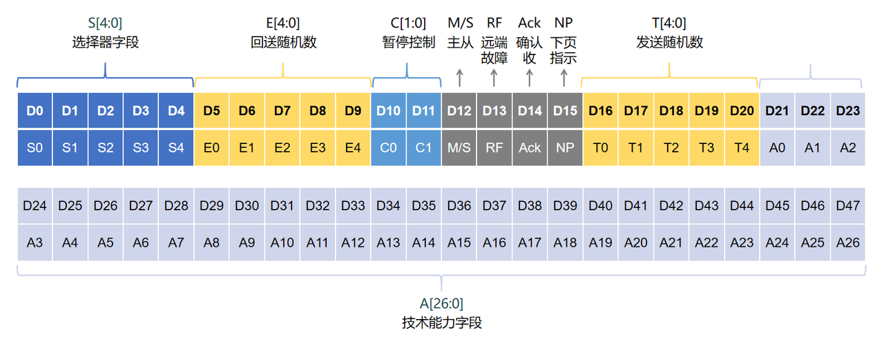
The entire data segment is divided into several functional fields:
- S[4:0] Selector Field: Identifies the type system of the current negotiation message. For example, when S[4:0] is
00001, it represents negotiation within the IEEE Std 802.3 system. Other combinations are reserved and prohibited from being sent. - E[4:0] Echoed Nonce and T[4:0] Transmitted Nonce: This is a handshake mechanism used to prevent deadlocks, which we will detail shortly.
- A[26:0] Technology Ability Field: Used to declare the speeds, duplex modes, and other capabilities supported by the local end.
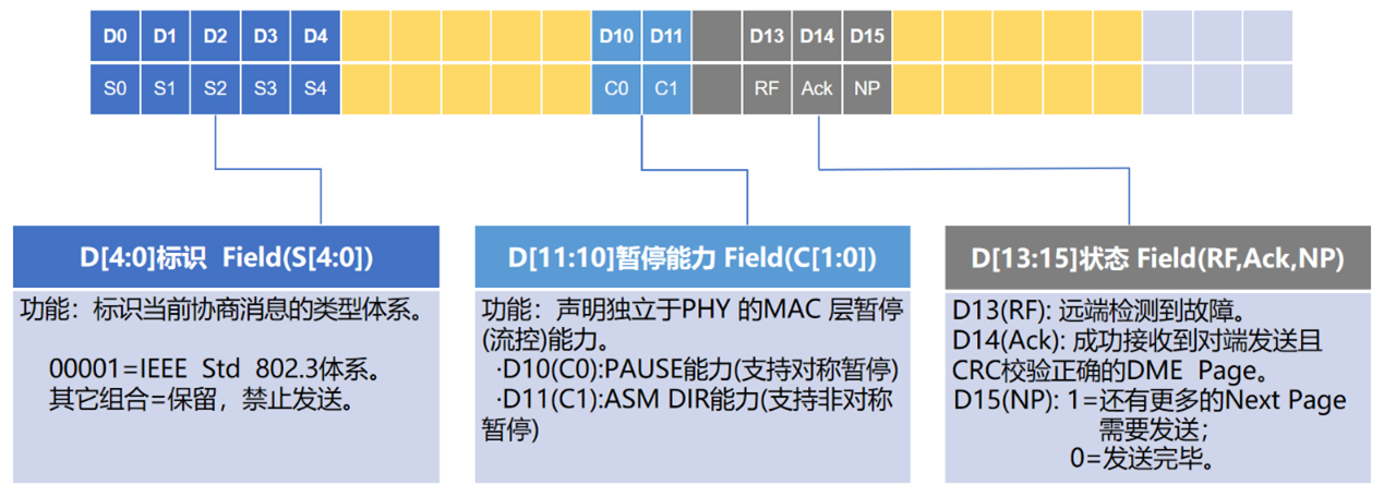
Critical status bits from D10 to D15 contain flow control and status indicators:
- Pause Ability C[1:0]: Declares MAC layer flow control capabilities independent of the PHY. D10 (C0) indicates support for symmetric pause; D11 (C1) indicates support for asymmetric pause (ASM DIR).
- Status Indicators:
- RF (D13): Remote Fault detected.
- Ack (D14): Acknowledges that a DME Page was successfully received from the remote end with a correct CRC.
- NP (D15): Next Page indicator. “1” means there are more Next Pages to send; “0” means transmission is complete.
4. Who is the Boss? Master/Slave Role Arbitration
In Ethernet communication, one end must provide the master clock (Master), while the other end recovers the clock (Slave). A core task of auto-negotiation is deciding who takes which role.
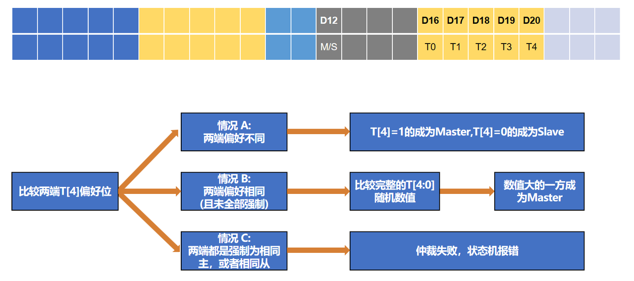
Arbitration is based on the T[4:0] field in the data segment.
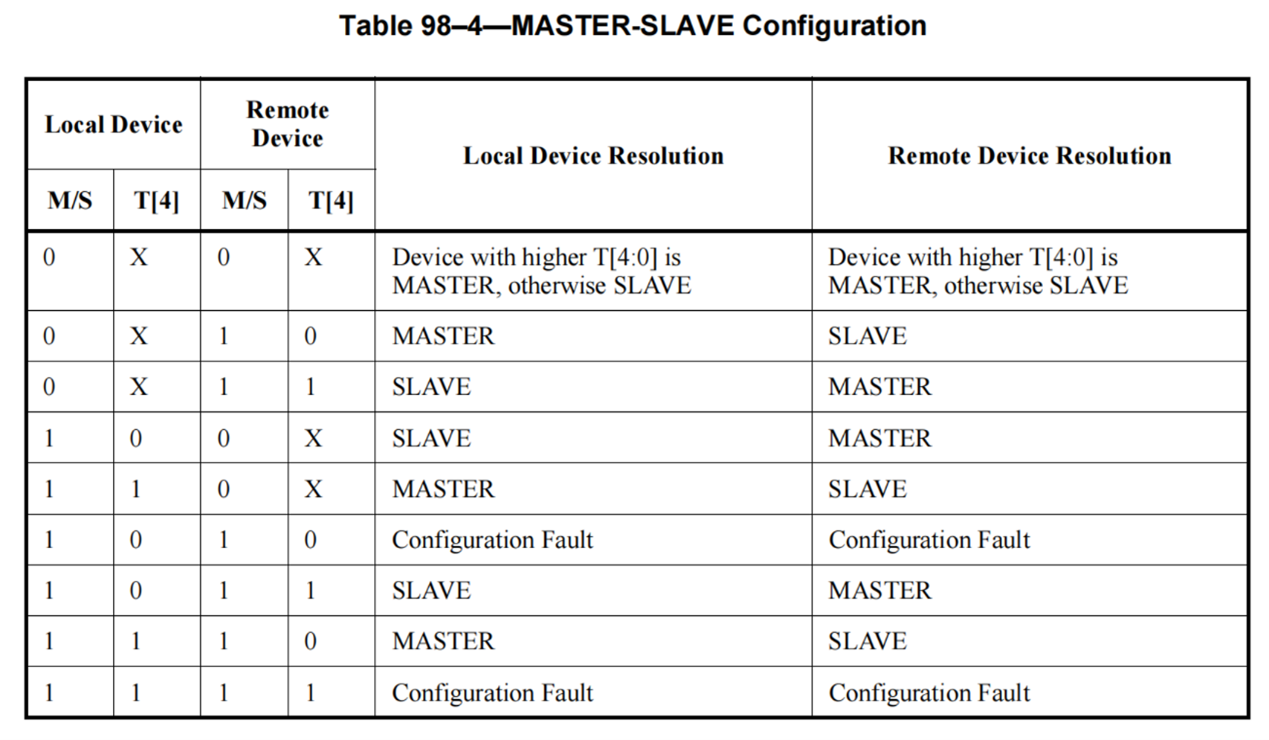
- T[4] is the preference bit: “1” represents a preference or forced requirement to be the Master; “0” represents a preference or forced requirement to be the Slave. In Case A (different preferences), roles are assigned directly according to preference. In Case B (same preference, but not forced), a “random number” tie-breaker is used: the system compares the full T[4:0] random values, and the party with the higher value wins to become the Master. In Case C (both sides forced to be Master or both forced to be Slave), arbitration fails and the state machine reports a Configuration Fault. The IEEE Table 98-4 above lists the arbitration results for various combinations.
5. Breaking the Deadlock: Anti-Deadlock Handshake (Nonce Exchange)
As mentioned, if T[4:0] is identical, the party with the higher value becomes Master. But what if the randomly generated T[4:0] values on both sides are exactly the same? This is where the anti-deadlock handshake mechanism comes in.
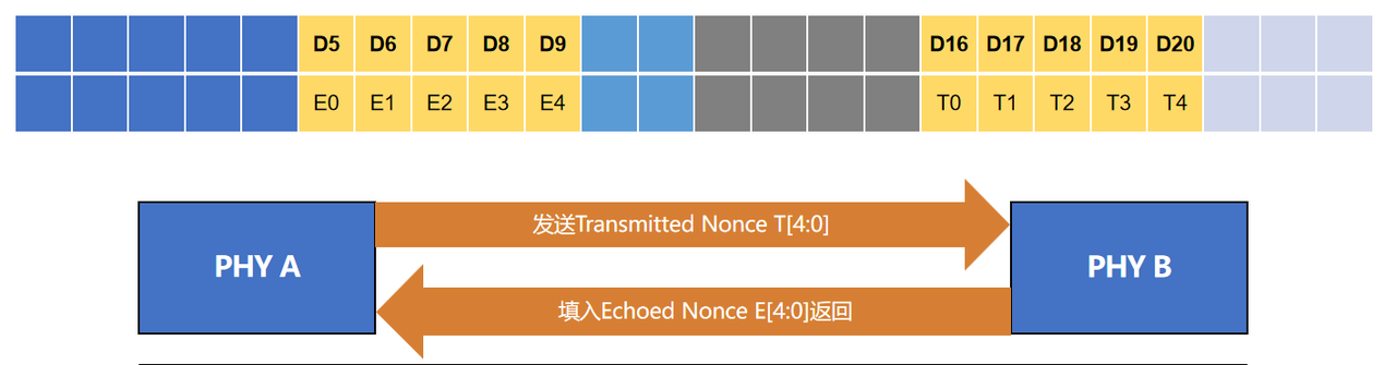
To prevent infinite loop deadlocks, the protocol stipulates:
- Transmitted Nonce T[4:0]: Every time the Ability Detect state is entered, a uniformly distributed pseudo-random number is generated (T[3:0] ranges from 0 to 15).
- Echoed Nonce E[4:0]: After a device receives a DME page with a correct CRC, it must extract the remote end’s T[4:0] and fill it into its own E[4:0] field for the return transmission. If no valid page is received, it is filled with all zeros.
- Nonce Match Logic: If PHY A finds that the received remote T[4:0] is identical to its own generated T[4:0], it must forcibly invert its own least significant bit T[0] and regenerate T[3:1]. This ensures the random numbers will be different in the next handshake, effectively resolving the deadlock.
6. Reaching Consensus: Technology Ability Set and the HCD Principle
After resolving the roles, the next step is determining the communication speed. This is where the A[26:0] Technology Ability Field comes into play.
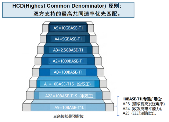
As shown in the “Ability Ladder” above, different bits represent different Automotive Ethernet speed standards:
- A0 = 100BASE-T1 ()
- A2 = 1000BASE-T1 ()
- A3 = 2.5GBASE-T1 ()
- A4 = 5GBASE-T1 ()
- A5 = 10GBASE-T1 ()
- A1/A22/A9, etc., correspond to specific speeds and duplex modes such as 10BASE-T1S/10BASE-T1L.
A vital principle followed here is the HCD (Highest Common Denominator) principle. Simply put, “the highest common speed supported by both parties is prioritized.” If Party A supports 100M and 1000M, and Party B supports 1000M and 2.5G, the final connection speed will be the highest common value—1000M. (Note: There are exclusive extension bits for 10BASE-T1L, such as A23 for requesting increased transmit levels, A24 for declaring high-level transmit/receive capability, and A25 for EEE energy-saving capability. Most other bits are reserved.)
7. Want More? Two Next Page Formats
If the basic Base Page is insufficient to express all technical capabilities and configurations (such as the NP=1 mentioned earlier), the PHY chip will continue to send Next Pages.
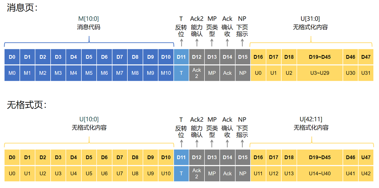
- Next Pages have two distinct formats, distinguished by the MP (Message Page) bit:
- Message Page: Contains a formatted message code M[10:0] and unformatted content U[31:0]. These pages are typically used to transmit specific, standard-defined information.
- Unformatted Page: Contains a larger capacity of unformatted content, covering the U[10:0] and U[42:11] regions. These pages leave ample room for vendor-specific configurations or transparent transmission of higher-layer protocol information.
Both page types retain control fields such as Ack (Acknowledge), NP (Next Page), Ack2 (Acknowledge 2), and T (Toggle bit) to ensure multi-page messages are received and parsed reliably and in order.
8. Conclusion
From the physical layer level transitions of DME to the “strategic maneuvering” within the 48-bit data segment, and the foresight of the anti-deadlock mechanism, the Automotive Ethernet auto-negotiation mechanism is a rigorous, sophisticated, and robust state machine. It is these invisible, millisecond-level handshakes that support the high-speed and stable operation of today’s massive data flows in intelligent vehicles.
After reviewing today’s hardcore underlying protocols, these 0s and 1s might seem distant. Don’t worry—in subsequent articles, we will link these underlying DME messages directly to the configurations you encounter daily in development and testing! For instance, which field corresponds to the “Master/Slave mode” we select in a testbench? How does our “100M/1000M speed” setting actually take effect through the HCD principle? We will combine actual configuration interfaces to help you bridge the gap from the application layer to the physical layer. Stay tuned!
We hope this article helps you better understand this seemingly dry but vital underlying technology of automotive networking! If you have more questions about Automotive Ethernet, feel free to join the discussion in the comments section.