1. Introduction: Why do cars need a “different” Ethernet?
1.1 Current challenges of in-vehicle networks
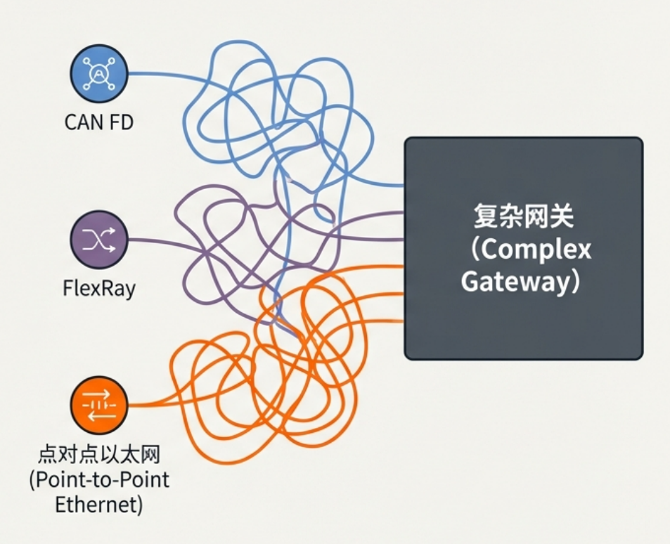
In today’s automobiles, the network architecture is like a technological “United Nations.” Multiple communication technologies coexist, each with its own role. For example, we have CAN FD networks for body control, FlexRay networks for high-reliability control, and point-to-point automotive Ethernet (such as 100BASE-T1 or 1000BASE-T1) for high-bandwidth infotainment and advanced driver assistance systems (ADAS).
This heterogeneous architecture presents a significant challenge: different technologies cannot communicate directly. To enable them to work together, engineers must design complex and expensive gateways. These gateways act as translators, converting data between different network protocols. However, the hardware and software of these gateways are not only costly but also frequently become a source of potential quality problems in vehicle production.
1.2 The Vision of an “All-Ethernet” Car
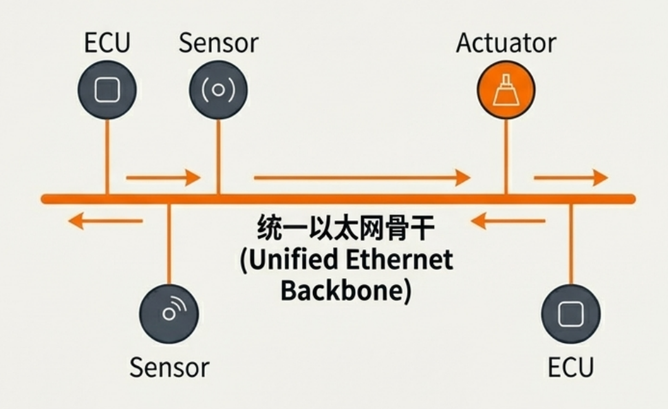
To address these challenges, the industry has put forward a compelling vision: to build a homogeneous network architecture entirely composed of automotive Ethernet, namely, an “all-Ethernet” car.
The core advantage of this vision lies in its simplification. If the entire vehicle uses Ethernet, we can fully leverage Ethernet’s mature addressing methods, such as MAC and IP addresses. Data can be automatically routed and forwarded throughout the vehicle network based on these addresses, just like in a home or office network. This significantly simplifies or even completely replaces complex and expensive dedicated gateways, thereby improving reliability and reducing costs.
1.3 Limitations of traditional Ethernet and the emergence of 10BASE-T1S
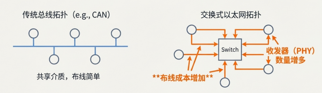
So why can’t we simply replace bus networks like CAN or FlexRay with existing automotive Ethernet? The answer goes far beyond cost. There are several fundamental reasons why traditional office Ethernet (such as 100BASE-TX) is unsuitable for automotive environments:
- Wiring and Cost: Traditional Ethernet typically uses four- or eight-wire cabling, while automotive buses (such as CAN) generally use twisted-pair cabling. Fewer cables mean lower cost and lighter weight. However, point-to-point or switched Ethernet topologies require more transceivers (PHYs), further increasing hardware costs.
- Electromagnetic Compatibility (EMC): The electromagnetic environment in automobiles is extremely harsh, with EMC requirements far exceeding those of consumer electronics. Standard Ethernet cannot meet these requirements.
- Power Modes: Vehicles have extremely low power consumption requirements when the engine is off to prevent battery depletion. Standard Ethernet lacks this ultra-low-power sleep mode.
- Wake-up Time: Onboard ECUs must be able to fully wake from sleep and be operational within 100 milliseconds, a capability that standard Ethernet cannot achieve.
To address these challenges, 10BASE-T1S was developed. It is an Ethernet technology designed specifically for automotive applications that supports bus (or multipoint) topologies, aiming to achieve the simplicity and efficiency of traditional bus networks using the language of Ethernet.
Having clarified the background of the creation of 10BASE-T1S, let’s delve into the specific characteristics of this technology.
2. What is 10BASE-T1S? A Quick Overview of its Core Features
The following table summarizes the key technical parameters of 10BASE-T1S:
| characteristic | describe |
| Technology Name | 10BASE-T1S |
| Data rate | 10 Mb/s |
| Network Topology | Multi-drop or Bus |
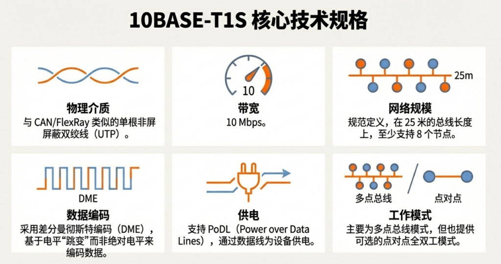
| Physical medium | The single-twisted pair is very similar to the cables used in traditional automotive buses such as CAN FD or FlexRay. |
| Nodes and Length | The IEEE standard specifies that the network should support at least 8 nodes and the bus length should be up to 25 meters. |
| Data Encoding | DME (DifferentiDME (Differential Manchester Encoding) is a technology that encodes data based on transitions rather than high or low levels. (This encoding method includes a built-in clock signal, which helps in more reliable data recovery at the receiving end.) |
Having understood these basic parameters, the most crucial question arises: how does 10BASE-T1S avoid data collisions on a bus network where all nodes share the same wire? This is thanks to its core mechanism—PLCA.
3. Core Mechanism: How Physical Layer Conflict Avoidance (PLCA) Works
3.1 The fundamental problem of bus networks
All bus technologies need to address the problem of signal collisions and information corruption caused by multiple nodes transmitting data simultaneously, and the solutions for in-vehicle networks vary:
- CAN networks use non-destructive arbitration: when multiple nodes send messages simultaneously, the node with the smaller ID (higher priority) gains bus access.
- FlexRay networks use time-sharing: each node is assigned a fixed time slot, and nodes only send data within their own time slot, avoiding conflicts at the source.
3.2 PLCA mechanism
The PLCA (Physical Layer Collision Avoidance) mechanism used in 10BASE-T1S applies the proven time-division concept of FlexRay to Ethernet. It avoids collisions at the source by precisely allocating a dedicated transmission time window for each node.
The PLCA mechanism includes the following core concepts:
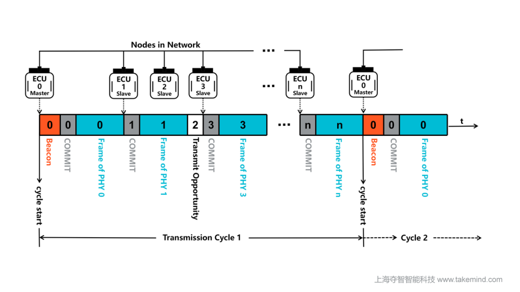
- Node ID: Each node in the network is assigned a unique ID number from 0 to N. This ID determines its transmission order within a communication cycle.
- Master Node: Typically the node with ID 0. It acts as the network coordinator, responsible for periodically sending “beacons” to initiate a new communication cycle.
- Beacon: A special signal emitted by the master node that marks the start of a new transmission cycle and synchronizes the time of all nodes on the network.
- Commit Symbol: If a node actually has data to send during its transmission opportunity, it will first send a “commit symbol.” This symbol is crucial; it’s like raising your hand at a meeting to indicate “I want to speak,” clearly indicating that it will occupy the bus. This behavior distinguishes it from nodes that simply let their transmission opportunities expire. After sending the commit symbol, the node immediately begins sending standard Ethernet data frames.
- Transmit Opportunity: After the master node sends the beacon, all nodes will be granted a dedicated time window to send data in strict order of their ID numbers from smallest to largest.
Having understood these basic concepts, let’s look at a few specific scenarios to see how PLCA works in actual communication.
4. PLCA in Practice: Analysis of Three Common Communication Scenarios
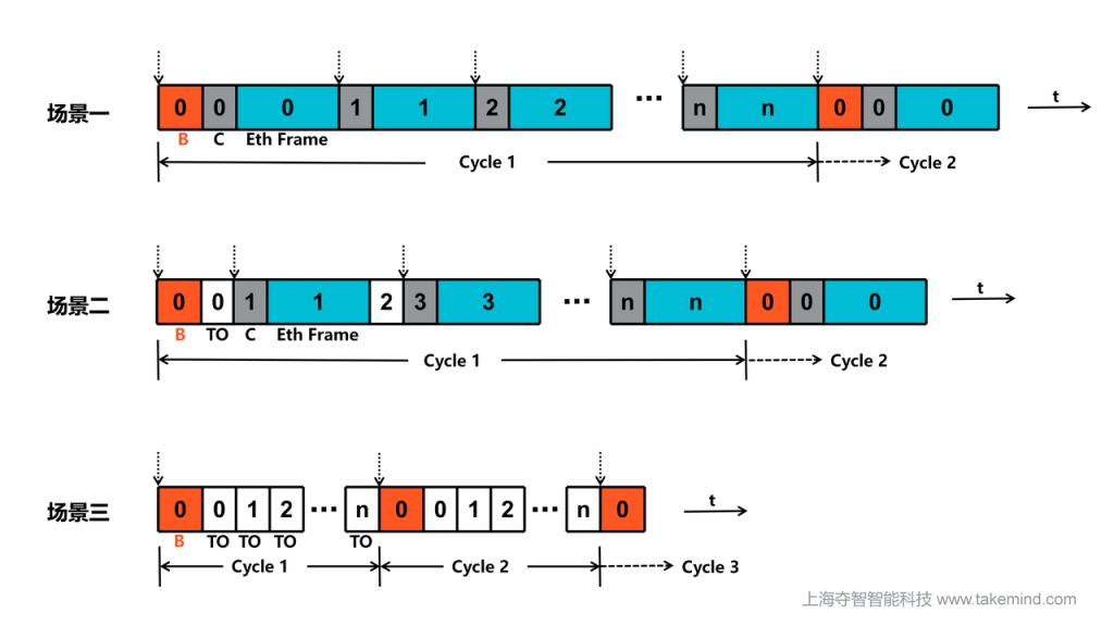
4.1 Scenario 1: All nodes are sending data
Under this full-load condition, all nodes in the network need to send data.
- Node 0 sends a beacon to initiate a cycle.
- Node 0’s transmission opportunity arrives. Since Node 0 has data to send, it immediately sends a commit symbol, followed by a complete Ethernet frame.
- When it’s Node 1’s turn, it also sends a commit symbol and its own data frame.
- This process continues until all nodes have finished polling.
4.2 Scenario 2: Some nodes are sending data (e.g., nodes 1 and 3)
In this more typical scenario, some nodes in the network need to send data.
- Node 0 sends a beacon to initiate the cycle.
- Node 0’s transmission opportunity arrives and expires (because it has no data to send).
- Node 1’s transmission opportunity then occurs. Node 1 has data to send, so it immediately sends a commit symbol, followed by a complete Ethernet frame.
- After Node 1 finishes sending, Node 2’s transmission opportunity arrives, but it has no data to send, and its opportunity expires.
- Node 3’s transmission opportunity then occurs; it also sends a commit symbol and its own data frame.
- This process continues until all nodes have finished polling.
4.3 Scenario 3: Network idle (no data being sent by any node)
This is the simplest case: the entire network is very quiet, and no nodes need to communicate.
- Node 0 (the master node) sends a beacon, initiating a new transmission cycle.
- Node 0’s transmission opportunity arrives, but since it has no data to send, it expires automatically after a short window.
- Node 1’s transmission opportunity then arrives, but similarly, it has no data to send, and its opportunity expires as well.
- This process continues sequentially until all nodes’ transmission opportunities have been polled and expired. Then, the master node sends a beacon again, starting the next cycle.
5. PLCA in Practice: Analysis of Two Optimized Communication Scenarios
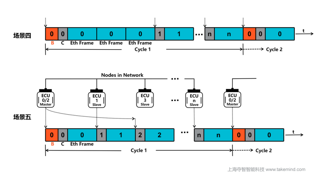
5.1 Scenario 4: Burst Mode
10BASE-T1S also offers an optional “Burst Mode” to handle asymmetric data flows. In many automotive applications, data flows are not uniform. For example, one sensor may be the primary data producer, while other nodes are primarily data consumers. Burst Mode allows a specific node to be configured to continuously send more than one frame of data within a single transmission opportunity. This significantly improves data transmission efficiency and meets the specific needs of nodes requiring high throughput.
5.2 Scenario 5: Multiple IDs on a Single Node
In addition to burst mode, PLCA offers more flexible approaches. Engineers can configure multiple IDs for a node requiring low latency or high bandwidth via software configuration. Furthermore, multiple IDs can be combined with burst mode. These strategies allow for fine-tuning of network performance, ensuring that critical data is prioritized for transmission, although this may increase transmission latency for neighboring nodes.
6. PLCA in Practice: Analysis of Special Scenarios
6.1 Scenario 6: A slave node (not ID 0) in the network unexpectedly loses power or goes offline.
Based on the polling principle of PLCA, when a regular slave node in the network is lost, the bus continues to operate as scheduled. When the scheduler gets a transmission opportunity for this lost node, since the node is no longer responsive, the bus will not stagnate and wait; the node’s time window will be skipped as if the network were completely idle, and the polling will immediately be passed to the next node.
- Network Stability: The overall network communication cycle and normal communication of other nodes remain unaffected. The bus simply skips over this “silent” node.
- Diagnostics: Although the PLAC physical layer continues to operate normally, upper-layer applications or network management protocols may detect the node’s heartbeat signal or periodic data loss, thus determining that the node is offline.
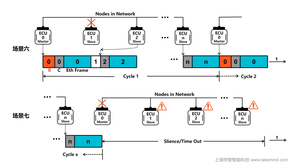
6.2 Scenario 7: The master node (PLCA coordinator) with ID 0 experiences an unexpected power outage or goes offline.
The loss of the master node is a more serious event because it is responsible for initiating the entire communication cycle. For slave nodes, the disappearance of the master node manifests as a prolonged, unconventional “silence.” When the master node goes offline, the network response process is as follows:
- Diagnosis: Some PHY chips have a beacon-not-received timing mechanism. If no beacon is received for a long time, it will determine that the master node has been lost and may disable the PLCA mechanism, falling back to the CSMA/CD model to prevent a complete interruption of network communication, but at the cost of the collision-free and deterministic advantages of PLCA. Alternatively, the application layer can recognize this error and start a backup master node to establish a new communication cycle.。
- Network Stability: Since the master node is the only device responsible for sending “beacon” signals, its loss means that no new beacons will be sent in the network. After the existing PLCA communication cycle ends, a new cycle cannot be started.
6.3 Scenario 8: There are two slave nodes in the network that have been misconfigured with the same ID.
When the PLCA scheduler reaches the opportunity to send the duplicate ID (TO), the two nodes will simultaneously preempt the bus due to their logical “legitimacy”.
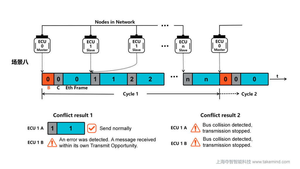
- Network Stability: Physical layer data collisions occur. Because two nodes simultaneously drive the bus, interference between electronic signals causes waveform distortion, preventing the receiver from parsing valid data (CRC checksum failure). Although overall network scheduling remains uninterrupted, the transmission efficiency of this specific ID and its immediately adjacent nodes will be significantly reduced due to collisions and potential carrier detection interference.
- Diagnosis: Relies on the real-time collision monitoring mechanism of the PHY chip. Relevant nodes will trigger register status bits:
RXINTO (Receive in Transmit Opportunity): The node received data within its own transmit window, indicating the presence of a “shadow” node.
TXCOL (Transmit Collision): The node detected an abnormal level during transmission, confirming a collision.
In practice, these two flags are invaluable tools for troubleshooting ECU flashing errors or production line configuration oversights, quickly pinpointing the problem to a specific ID conflict.
6.4 Scenario 9: There are two nodes in the network that are misconfigured as ID 0.
This is the most serious logical conflict in a PLCA network because both nodes will try to gain control of the bus and set the clock cycle.
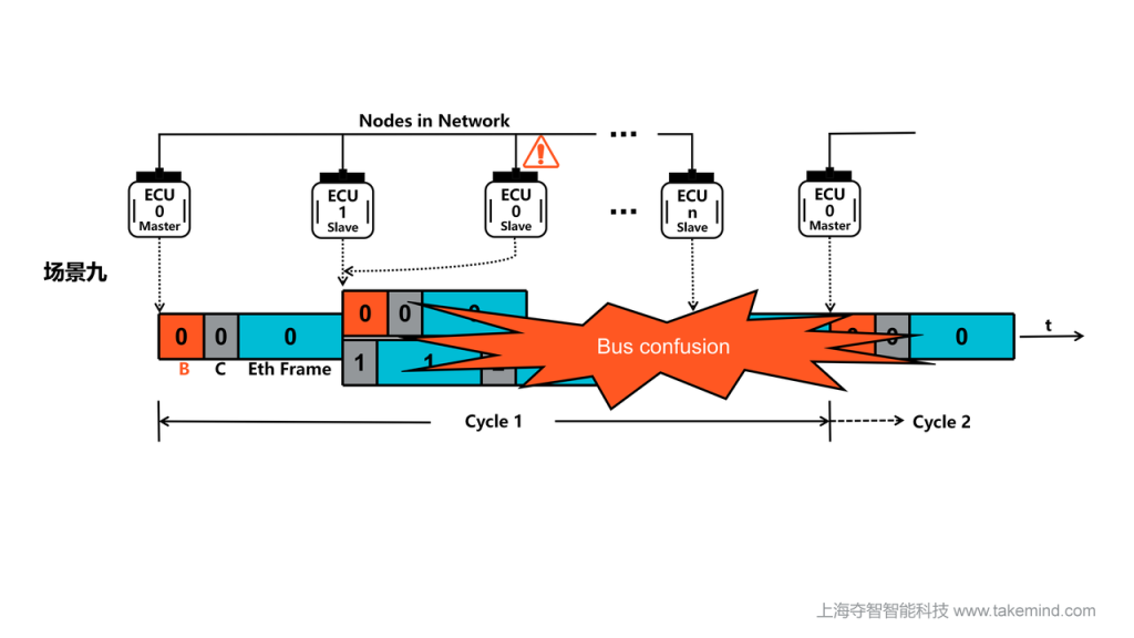
- Network Stability: Synchronization reference failure. The two master nodes send beacons according to their respective internal clocks, causing overlapping or out-of-order beacon signals on the bus. Slave nodes will be unable to lock onto a unique synchronization frequency, resulting in complete timing disruption throughout the PLCA communication cycle, rendering the network unusable.
- Diagnosis: The PHY chip has a “multi-master node detection” capability. When a node configured as ID 0 receives another beacon outside of its own transmission time, it will trigger:
UNEXPB (Unexpected BEACON Received): This status bit is immediately set in the Status 1 (STS1) register, explicitly indicating a master node configuration conflict in the network. This is the primary starting point for troubleshooting network initialization failures.
6.5 Scenario 10: The total number of nodes configured in the master node is less than the highest node ID in the network.
For example: IDs 0-6 actually exist, but the MAX_ID (Node Count) of the master node is incorrectly set to 3.
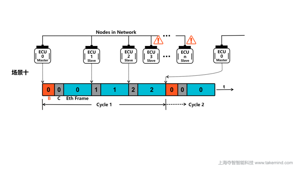
- Network Stability: High-order ID nodes are “muteed.” After the master node’s transmission opportunity at ID 2 ends, it ignores subsequent nodes and forcibly sends a new beacon to start the next cycle. This causes nodes with IDs 3-6 to logically never get their transmission opportunity, resulting in partial network service malfunctions.
- Diagnosis: Affected slave nodes (skipped nodes) have self-awareness. When these nodes receive a new beacon before their transmission window arrives, it triggers:
BCNBFTO (BEACON Received Before Transmit Opportunity): This status bit is set in the STS1 register, directly proving that the master node’s Node Count configuration does not match the physical topology. This provides direct evidence for parameter optimization during system integration.
Through these scenarios, we see how PLCs elegantly coordinate communication. So, what practical benefits does 10BASE-T1S bring compared to traditional point-to-point Ethernet?
7. Advantages and considerations: Why choose 10BASE-T1S?
7.1 Core advantages
Compared to traditional point-to-point switched Ethernet, 10BASE-T1S offers significant advantages:
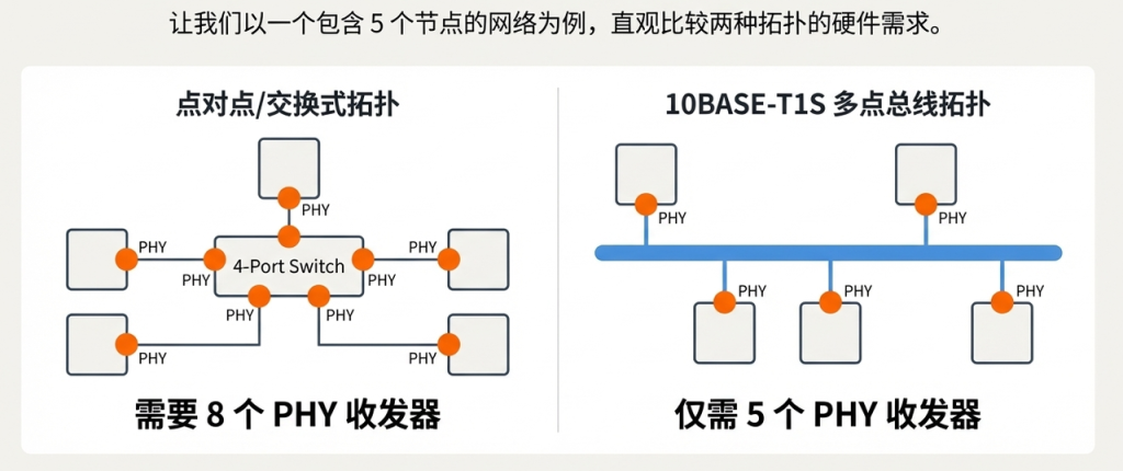
- Reduced hardware costs and wiring weight: This is the most direct benefit. For a simple example, connecting five ECUs using a multi-point bus topology like 10BASE-T1S requires only five transceivers (PHYs), one for each ECU. In contrast, a switched point-to-point solution would require ten PHYs (one for each of the five ECUs, plus one for each of the five ports on the central switch). Fewer PHYs and simpler wiring translate to lower costs and a lighter overall vehicle weight.
- Driving an all-Ethernet architecture: 10BASE-T1S fills a key gap in the Ethernet technology landscape. It enables all automotive applications, from high-bandwidth technologies like Gigabit Ethernet to low-cost sensors/actuators (10BASE-T1S), to be covered by a single, unified technology (Ethernet). This significantly simplifies the overall vehicle network architecture, paving the way for a truly “all-Ethernet” car.

7.2 Engineering Practice: Exceeding Standard Limitations
While the IEEE standard guarantees that a network “supports at least 8 nodes,” this is not a hard limit. Research by Ford Motor Company shows that in practical engineering, with careful design, networks can stably support more nodes. This provides valuable practical guidance.
The key physical layer factors affecting the maximum number of nodes are mainly two:
- Node Capacitance: Each node (including the PHY, connectors, ESD protection devices, etc.) introduces a capacitive load to the bus. The standard’s assumption of 8 nodes is based on a capacitance of 25pF per node. Using low-capacitance components to control the capacitance of individual nodes to 20pF or lower is fundamental to achieving higher node counts.
- Node-to-node Distance: The physical spacing between nodes on the bus significantly affects signal reflection and overall signal integrity. Stacking nodes too close together degrades signal quality.
Based on these factors, Ford’s research provides specific quantitative recommendations for network topology design:
- 8 nodes: Minimum node spacing 0.5 meters
- 8-10 nodes: Minimum node spacing 0.75 meters
- 10-15 nodes: Minimum node spacing 1 meter
- 15-20 nodes: Minimum node spacing 1.5 meters
This insight translates theoretical standards into actionable engineering guidelines: by optimizing topology design and component selection, stable networks with more than eight nodes are entirely possible. Of course, the final design must undergo rigorous signal integrity testing to ensure all specifications meet requirements.
Now that we have a comprehensive understanding of what 10BASE-T1S is, how it works, and its advantages, let’s summarize what we’ve learned today.
8. Summarize
10BASE-T1S is a highly innovative automotive Ethernet technology. It cleverly combines the simplicity and cost advantages of traditional bus networks (such as CAN) in terms of physical cabling with the powerful functionality and flexibility of the standard Ethernet protocol ecosystem.
Through its unique PLCA (Physical Layer Collision Avoidance) mechanism, 10BASE-T1S achieves deterministic, collision-free communication over a shared single pair of twisted-pair cables. It is not only a strong competitor to traditional networks like CAN, but also directly rivals emerging standards like CAN XL, providing a crucial foundation for a simpler, more efficient, and more cost-effective “all-Ethernet” automotive network architecture in the future. As automotive electronic and electrical architectures continue to evolve, this technology will undoubtedly play an increasingly important role in future intelligent vehicles.